 The idea is to sufficiently cool the charge air going into the engine so that the boost pressure can be safely increased in order to produce more power. The standard pressure at full boost on the Ghibli is about 1.2 bar. I'm currently running a little more than this with the help of the Turbosmart E-Boost 2 electronic boost controller. Using this boost controller, it's possible to increase the boost pressure to as much as 2.75 bar, but this would produce so much heat and pressure that the engine would quickly detonate. However, with sufficient cooling of the charge air, the engine should be able to comfortable operate with 1.4 bar, which would be the target inlet pressure after installing the water injection system.
The water injection system of choice is ERL's Aquamist 2d system pictured above. A schematic of this system is pictured below.

What's missing from this system is a water storage tank; I still don't understand why ERL don't offer a purpose designed water tank for this system, although I understand that it's assumed that the system will be tied into the car's windscreen washer tank, with the low pressure pump that supplies water to the washer nozzle acting as a primer pump for the high pressure water injection pump. There's a couple of reasons why this setup isn't ideal for the Ghibli. The main one is that the battery on the Ghibli is located in the boot of the car. Since the water injection pump draws a fair amount of current, it ideally needs to be located pretty close to the battery, otherwise some pretty thick gauge wire needs to be run from the boot of the car to the engine bay, sufficient to accomodate the required current supply to the high pressure pump. I've had some bad experience running cable between the front and the back of the car... I used to have a VW Corrado G60 a while back and the unscrupulous previous owner had left some wiring exposed in the boot, presumably from a large bass speaker that he'd installed. One day I was driving down the motorway when the car filled up with smoke... the exposed wires had formed a circuit, resulting in the wire insulation burning. Fortunately I managed to pull onto the hard shoulder and sort the problem out, but it's not an experience I'd like to repeat any time soon. I can't think of the second reason off the top of my head, but bottom line is that I'd locate the pump in the boot.
 Having determined that I want the pump in the boot, that means sourcing a dedicated water tank to supply the water. Since I want to minimise the amount of hose being routed around that car and I'd prefer a reliable gravity feed between the water tank and the pump (to increase reliability and robustness of the system), the water tank ideally needs to be located in close proximity to the pump. This implies mounting the pump in the boot next to the pump. After searching around for decent water tanks (which is more difficult than it sounds) I've come to the conclusion that a modified version of the Forge fuel tank pictured here would be a suitable solution. This is a 2 gallon tank, which is about 7.6 liters. The Ghibli fuel tank holds about 70 liters (might be 80? can't remember off the top of my head). Therefore, the water tank is about 10% of the fuel volume, which is a good ratio if you're going to be driving with the Aquamist system running all the time since it means worse case you need to fill up the water tank when you fill up the fuel tank. I don't envisage driving this hard though, so the water should last a few fuel top ups.
 The location of the ports would need modifying a bit; I'd want some lugs adding to it onto which I can fasten the ERL pump and I'd also want a fitting added so that I could install the low level safety switch pictured here. I'd probably get the Aquamist kit from Turbobits since the guy who runs this online shop owns a Maserati on which he's tinkered with the boost controller and installed a first generation Aquamist system which he's documented on his site here. He also sells lots of ancillary bits and bobs that would be required for the Ghibli install.
 Having installed the pump and the tank in the boot of the Ghibli, I'd run a 6mm high pressure hose from the boot to the engine bay, probably running down the passenger side of the interior of the car and through a hole in the firewall. The nice thing about running a long length of hose from the pump to the nozzles is that the hose effectively acts as an anti-surge accumulator, negating the requirement for the item shown on the left; the hose will baloon slightly as the pressure increases inside it... the longer the hose, the greater the balooning volume, so a decent lengthed hose will dampen the pressure spikes of the system. Therefore, to utilise the hose as an anti-surge accumulator, the manifold would need to be located in the engine bay.
Rather than utilise the adjustable pressure switch that is included in the Aquamist 2d kit, I'd utilise the E-Boost to activate the water injection system. The E-Boost can be programmed to activate outputs at user defined pressures and since the boost controller already monitors inlet pressure, there's no point installing an additional potential leak path to the boost system. So the output from the E-Boost would be connected to the Aquamist manifold and set it to crack open at, for example, 1.0 bar.
The nice thing about utilising the E-Boost unit is that it can also be tied into the low level trigger on the water tank. The E-Boost has the facility to operate in three distinct modes. Using it in conjunction with the Aquamist system would require two of these modes to be utilised. The first would be the fail safe mode. The low level switch would be set such that when there's no water in the tank, it returns a zero logic (hence acting as a fail safe in the event that there's loss of power to the Aquamist system). When the E-Boost receives a 0 logic state from the low level switch, it would switch to the default operating mode, running the standard 1.2 bar boost pressure on the assumption that no water is available for injection into the inlet system.
When there's sufficient water in the tank, the low level switch will return a logic state of 1 to the E-Boost. This logic state will switch the E-Boost to water injection mode and enable a boost pressure of 1.4 bar (for example). As an added safety feature, the blocked nozzle detection system of the Aquamist FiA2 controller will control a relay on the low level switch circuit. The relay will be normally open, necessitating that the FiA2 keep it closed under normal operating conditions and hence acting as a fail safe in the event that the Aquamist system looses power. If the FiA2 detects that there's no water flowing through the injection nozzles, then the relay will open and the E-Boost will switch to default mode, operating at 1.2 bar.
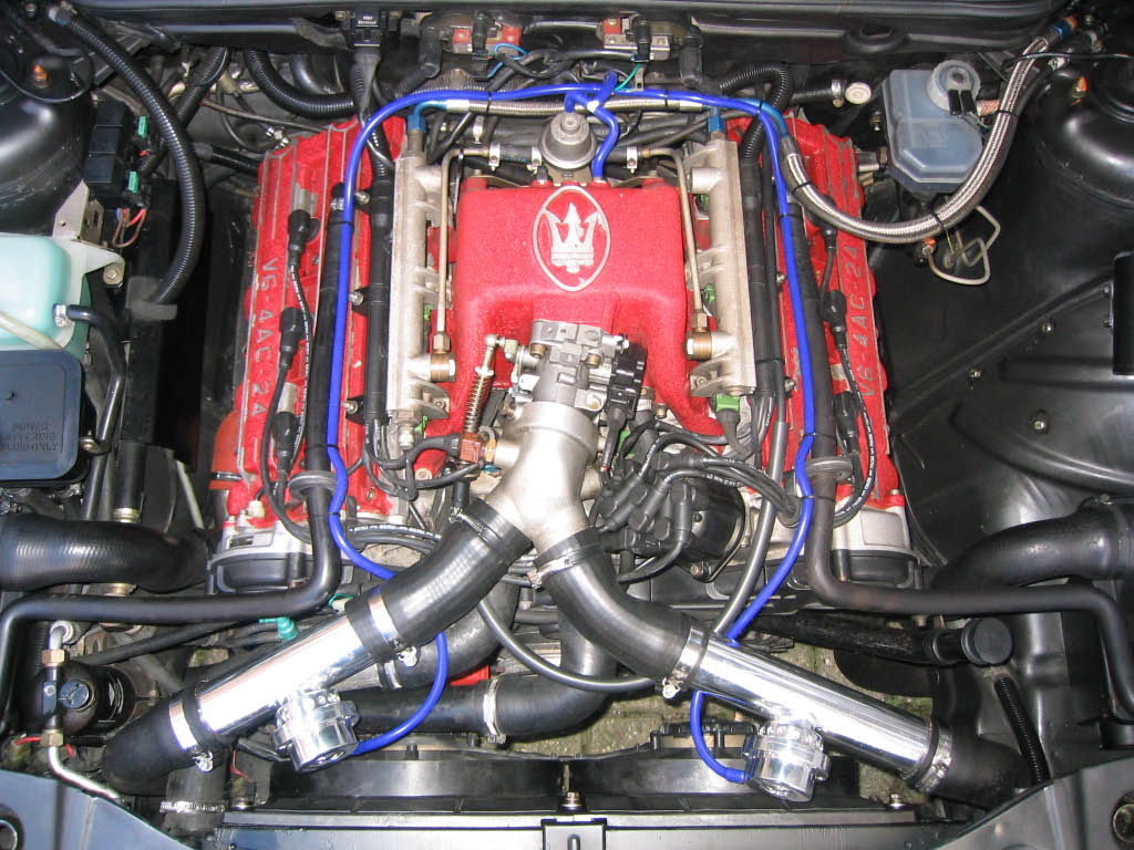
As you can see from the picture above, the Ghibli has two intercoolers and hence two inlet hoses that meet at a Y-piece at the throttle body. To get a good mixture of water and air, but also injecting as close to the plenum chamber as possible, I'd install two injection nozzles, one on each of the inlet "pipes" just upstream from the Y-piece. The shiny tube sections shown in the picture were manufactured to order from Forge motorsport in the UK and have the blow off valves welded directly onto them. I'd send these back to Forge and ask them to weld some additional material onto the tube and then drill and tap it at an appropriate size in order to install the nozzles. I'd locate the nozzles just downstream of the blow off valves in order to prevent water spray from being blow into the engine compartment.
In order to operate two nozzles, I'd require a Y-piece to be installed just downstream of the high speed valve included in the Aquamist kit. I'd want to locate this Y-piece as close as possible to the nozzles and make sure that the hose lengths from the Y-piece to the nozzles were of equal length. I'd also step down the hose size after the Y-piece to 4mm to help maintain the pressure between the manifold and the nozzle. After some communication with ERL via Turbobits, it appears that it's not necessary to run two high speed valves with two nozzles. If one nozzle blocks up, then more flow will pass through the remaining nozzle which should be sufficient to keep the charge cool. If the remaining nozzle then blocks up, the FiA2 module will detect it and send an error signal to the E-Boost to switch to fail safe mode.
So there you have it. That's the theory... just need to put it into practice. Can't see myself having time this year, but probably next year. Maybe Aquamist will have bought out a new system by then though!
No comments:
Post a Comment